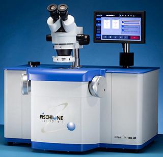
[custom_headline type= »left » level= »h1″ looks_like= »h2″]SEM Mill – Model 1061[/custom_headline]
A state-of-the-art ion milling and polishing system. It is compact, precise, and consistently produces high-quality scanning electron microscopy (SEM) samples in the shortest amount of time for a wide variety of applications.
- Two independently adjustable TrueFocus ion sources
- High energy operation for rapid milling; low energy operation for sample polishing
- Ion source maintains its small beam diameter over a wide range of operating energies
- (100 eV to 10 keV)
- Adjustable 10-inch touch screen with a user- friendly interface for simple setup of milling parameters
- Create pristine cross-section samples with the Cross-section station (optional)
- Independent ion source gas control
- Adjustable milling angle range of 0 to +10°
- In situ viewing and image capture during milling
- Sample rocking or rotation with ion beam sequencing
- Automatic termination by time or temperature
- Liquid nitrogen-cooled sample stage (optional)
- Vacuum or inert gas transfer capsule (optional)
ION MILLING
Ion milling is used in the physical sciences to enhance the sample’s surface characteristics. Inert gas, typically argon, is ionized and then accelerated toward the sample surface. By means of momentum transfer, the impinging ions sputter material from the sample at a controlled rate.
Advanced sample preparation
For many of today’s advanced materials, analysis by SEM is an ideal technique for rapidly studying material structure and properties. Fischione Model 1061 SEM Mill is an excellent tool for creating
the sample surface characteristics needed for SEM imaging and analysis.
Accepts large sample sizes
The SEM Mill accepts the following sample sizes:
- Cross section* Maximum:
0.39 x 0.39 x 0.157 in. (10 x 10 x 4.0 mm)
Minimum:
0.12 x 0.12 x 0.028 in. (3 x 3 x 0.7 mm) - Planar
1.25 in. diameter x 1 in. height (32 x 25 mm)
Automatic sample thickness sensing maximizes throughput, while magnetic encoding provides absolute positioning accuracy.
Cross-section station (optional)
The Fischione Instruments’ Cross-section station is a tool for creating pristine cross-section samples ready for ion milling in the SEM Mill.
The station enables precise positioning of the area of interest and can be used with a wide variety of materials, including semiconductor devices, multilayers, ceramics, and hard/brittle materials. e prepared region of interest is at and free from damage for subsequent SEM imaging and analysis.
High-quality cross-section samples can be produced quickly and easily by xing a mask to a sample in the user-friendly loading station. is sample preparation method preserves the quality of the inner layers and allows imaging and analysis of the material in its native state.
The station is designed to accommodate a wide range of sample sizes; the alignment of the mask and the sample is done both laterally and angularly.
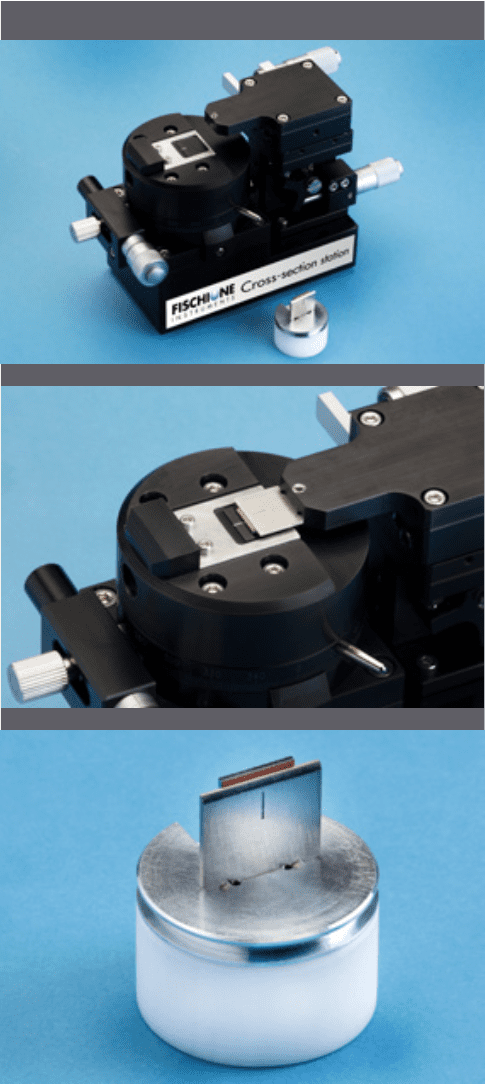
CROSS-SECTION SAMPLES MADE EASY – Fischione Instruments’ Cross-section
station (top) is an optional tool for the fast creation of pristine cross-section samples. The station allows precise positioning of the area of interest (middle) – x, y, and θ. The resulting cross-section sample (bottom) is ready for ion milling in the Model 1061 SEM Mill.
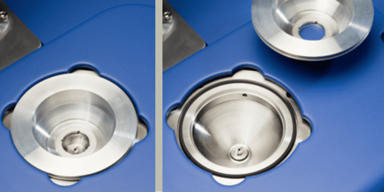
LOAD LOCK – Load lock closed (left) and load lock opened (right).
Quick sample transfer
The SEM Mill features a vacuum load lock
for rapid sample exchange. e load lock is ergonomically designed; simply lift the load lock cover to load the sample holder onto the stage.
Replace the cover and evacuation of the load lock occurs within a few seconds. e vacuum secures the load lock cover in place during ion milling. An electronically controlled elevator then moves the sample into the milling position.
At the conclusion of the milling process, the sample holder returns to the load lock, but remains under vacuum until vented by the user. Venting takes only a few seconds.
Vacuum or inert gas transfer capsule (optional)
An optional vacuum capsule allows you to transfer the sample to the SEM under vacuum or in an inert gas.
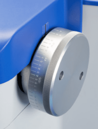
Precise angle adjustment
The ion sources are tilted to provide the desired milling angle. e continuously adjustable ion source tilt angles range from 0 to +10°. e ion source angles are adjusted using the left and right ion source controls.
You may choose to use one or both of the TrueFocus ion sources. If you are using both ion sources, you can adjust the beam angles independently.
When both ion beams are directed to one of the sample’s surfaces, milling rates are doubled; this capability is useful for applications such as planar polishing of samples.
Automated milling angle adjustment (optional)
Automated milling angle adjustment using the touch screen is an available option for the SEM Mill. Adding this capability enables you to create multi-step milling sequences that include the automatic adjustment of milling angles throughout the milling process.
MILLING ANGLE ADJUSTMENT
The base Model 1061 SEM Mill is equipped with manually adjustable milling angle controls for both ion sources. The milling angle of each ion source is independently adjustable. Automated milling angle adjustment, which is controlled through the SEM Mill’s touch screen, is optional.
Chamber
The SEM Mill’s vacuum chamber remains under continuous vacuum during operation. A load lock isolates the high chamber vacuum from ambient during sample exchange, ensuring optimal vacuum conditions.
Programmable sample motion
Sample rotation is 360° with variable rotation speed and a sample rocking feature. The instrument automatically senses the sample thickness and establishes the milling plane, which maximizes throughput. A magnetic encoder provides absolute positioning accuracy.
Integrated stage cooling (optional)
Although milling at low angles with low ion beam energies reduces sample heating, temperature-sensitive samples may require further cooling. Liquid nitrogen cooling of the sample stage is very e ective in eliminating heat-induced artifacts. The SEM Mill can achieve temperatures better than -170 °C.
The SEM Mill’s liquid nitrogen system features a dewar located within the enclosure that is fully integrated and interlocked. The dewar is positioned near the operator for easy access. Two dewar options are available: a standard dewar for applications that require 3 to 5 hours of cooling during ion milling, or an extended dewar for applications that require 18+ hours of operation under cryogenic conditions. Temperature is continuously displayed on the touch screen.
Automatic termination
The ion milling process can be automatically terminated by elapsed time or by temperature.
Time
A timer allows milling to continue for a predeter- mined time and then turns o the energy to the ion sources when the time has elapsed. The sample remains under vacuum until the load lock is vented.
Temperature
The thermal safeguard associated with the sample cooling system will stop the process if the sample stage reaches a preset temperature.
[text_output]
Specifications
| Ion source | Two TrueFocus ion sources Variable energy (100 eV to 10.0 keV) operation Beam current density up to 10 mA/cm2 Beam current density up to 10 mA/cm2 Milling angle range of 0 to +10˚ Choice of single or dual ion source operation Manual or motorized (optional) ion source angle adjustment Independent ion source energy control Adjustable spot size Faraday cups for the direct measurement of beam current from each ion source; allows optimization and adjustment of the ion source parameters for specific applications |
| Sample stage | Sample size: • Cross section* Maximum: 0.39 x 0.39 x 0.157 in. (10 x 10 x 4.0 mm) Minimum: 0.12 x 0.12 x 0.028 in. (3 x 3 x 0.7 mm) • Planar 1.25 in. diameter x 1 in. height (32 x 25 mm) Automatic sample thickness sensing to establish the milling plane and maximize throughput Automatic sample thickness sensing to establish the milling plane and maximize throughput 360˚ sample rotation with variable rotation speed Sample rocking Magnetic encoder provides absolute positioning accuracy |
| Cross-section station (optional) | Produces pristine cross-section samples Allows precise positioning of the area of interest – x, y, and θ Effective for use with a wide variety of materials, including semiconductor devices, multilayers, ceramics, and hard/ brittle materials Prepared region of interest is flat and free from damage for subsequent SEM imaging and analysis Accommodates a wide range of sample and mask sizes: • Sample and mask align both laterally and angularly • Multiple uses from a single mask |
| Sample cooling (optional) | Liquid nitrogen conductive cooling with integral dewar and automatic temperature interlocks Dewar access positioned close to instrument operator Ability to program and maintain a specific temperature between ambient and cryogenic Choice of: • Standard dewar capacity (3 to 5 hours of cryo conditions • Extended dewar capacity (18+ hours of cryo conditions) |
| Automatic termination | Automatic termination by time or temperature |
| Vacuum system | Turbomolecular drag pump and an oil-free, multi-stage diaphragm pump Vacuum sensing with a cold cathode, full-range gauge |
| Vacuum or inert gas transfer capsule (optional) | Allows transfer or storage of a sample at vacuum or in an inert gas environment |
| Process gas | UHP argon (99.999%); nominal 15 psi delivery pressure required Automatic gas control using two mass flow controllers |
| User interface | Instrument operation controlled via 10-inch, ergonomically adjustable touch screen Stack light indicator for determining milling operations status from a distance (optional) |
| Microscope (optional) | Load lock window accommodates the following microscopes: • 7 to 45X stereo microscope attachment for direct specimen observation • 525X high-magnification microscope and CMOS (complementary metal oxide semiconductor) camera system for site-specific image acquisition and display • 1,960X high-magnification microscope and CMOS camera system for site-specific image acquisition and display |
| In situ viewing and imaging | Sample can be monitored in situ in the milling position when using either the stereo or the high-magnification microscope Viewing window protected by a programmable shutter that prevents buildup of sputtered material and preserves the ability to observe the sample in situ |
| Sample illumination | Both the high-magnification and stereo microscopes have light sources that provide top-down, user adjustable, reflected sample illumination |
| Enclosure | Width (includes room on either side for service access: 50 in. (127 cm) Height: • Minimum height (without microscope or stack light options): 32 in. (61 cm) • Maximum height (with stack light option): 38 in. (77 cm) Depth (includes room for service access and exhaust fan air flow): 40 in. (102 cm) Enclosure design offers easy access to internal components when performing maintenance tasks |
| Weight | 161 lb. (73 kg) |
| Power | 100/120/220/240 VAC, 50/60 Hz, 720 W |
| Warranty | One year |
[/text_output]
